There are lots of web documents and pages about amateur amplifier projects. This amplifier is similar to the rest of them, this page is
a quick overview of my project. It shows the basic steps that I went through during construction. Making things is fun and there is nothing
more satisfying than seeing your project come to life.
I wanted a simple, robust amplifier with enough reserve to make FSK operation and EME activity possible without worrying that anything is too stressed.
The Russian GS35b is a proven triode tube that will deliver a solid 1.5Kw without hassle and running at sensible levels will deliver a clean signal.
this is the completed amplifier in its cabinet
Mounting the valve
It's perfectly normal to mount the valve directly to the RF deck chassis. Just drill a hole of the right size and use "L" shaped brackets
to hold the grid ring to the chassis. This is how some commercial amplifiers are made and they work well enough.
So why bother making anything more complex? Well.. the valve does need a fair bit of cooling near to the Cathode and Grid connections. In the past I have used temperature
sensitive paint on these commercial amps and under heavy drive conditions the ceramic seals are operating way past their maximum rating. OK.. so are the maximum ratings important?
I believe they are for two reasons, first we have a choice, we _can_ design a socket that keeps the tube working within its design tolerance
so the tube stands a good chance of lasting longer, Russian Triodes are very cheap... now... how long will they be cheap once supplies run short. We invest a lot of time into building these
projects, why on earth would we skimp on caring for the tube?
The second reason is that the tube tuning point changes as the tube gets (too) hot in use, using a suitable mounting arrangement reduces the need to re tune the amplifier and improves the linearity
in use. The linearity of the GS31 and GS35 isn't fantastic to start with, I consider them to be similar to the Rover V8 engine of the amplifier world :-)
The system employed in this amplifier spaces the tube below the amplifier chassis in order that an air flow can be created around the cathode and grid seals. This can be done in many ways
such as lowering the grid below the chassis using tubular spacers. I prefer the method used here as it provides a solid mount for the tube and a low inductance connection from the
grid ring to the RF chassis. Use of a heavy section of copper for the mount also helps conduct heat from the valve into the chassis where the forced air cools the whole assembly.
The copper plate is cut to size and legs are fitted between the grid plate and the chassis. These legs are drilled to allow airflow through them but the majority of the airflow is through the two open sides.
The legs are attached by short M3 screws from each side and when assembled the legs are silver soldered to the plate.
Tapping the holes M3 right through the copper plate wasn't pleasant and yes.. I did break a tap!
I'm told that milk is a good lubricant for tapping copper and I will try that next time.
The grid ring is formed from a piece of aluminium that is machined out to sandwich the valves grid ring to the copper grid plate. After machining
this is then cut into two halfs and the plate drilled and tapped to take CSK M3 screws.
the picture below shows this far better than words.
The only remaining choice is how to blow air past the tube and out through the anode cooler.
You can blow air into the grid compartment an let it exit past the valve and through the anode cooler or you can pressurise the anode compartment
and let most of the air pass through the anode cooler. By controlling the size of the ventilation holes in the grid compartment you can arrange to
direct a cooling jet of air directly onto the valve seals. Placing a vent hole near to the controller board will let some air pass over the heatsinks
for the bias and control circuits. In 19" racks its possible for air to be trapped in small none moving pockets and this system helps keep the air moving.
Whilst he air that exits the grid compartment is warmer than ambient, its fast moving and there is lots of it.
I chose this approach as the blower I have selected ( Airflow Developments
45CTL ) has enough flow to do this.
The grid compartment holds no surprise, simple input matching and bifilar heater choke. I tried a toroidal heater choke but it didn't work out for me. Construction tip, put a layer of heatshrink tubing on the ferrite rod
to protect the enamel on the wire that is easily damaged when winding this coil.
Use of a reasonable quality relay on the input is important to preserve the thru return loss when the amp is bypassed. This is of greater importance to me than any QSK ability.
The anode compartment contains a simple pi-l arrangement. The anode tune capacitor is a Jennings 20-200pf tx capacitor 50mm x 50mm x 50mm This capacitor is then modified as every second plate is removed. This
makes a nice wide spaced capacitor with 10 - 30pf of range.
Why not use a vacuum variable for this task? I don't believe they are necessary for this application and one flashover usually signals the end of these devices. This would be a little frustrating 30 minutes into a contest. An air spaced variable
modified in this way will stand the voltage and in the unlucky event of a flashover it stands a good chance of a "field" repair.
To reduce the losses and provide good returns for current within the anode compartment the chassis is lined with copper sheet. Ok at 50Mhz this isn't strictly necessary but it does look nice :-)
The load capacitor is a surplus 120pF wide spaced capacitor that I had on hand, by calculation it's a bit small but so far this hasn't proved to be the case in practice. If it does become an issue I will put a 50pF NP0 across it.
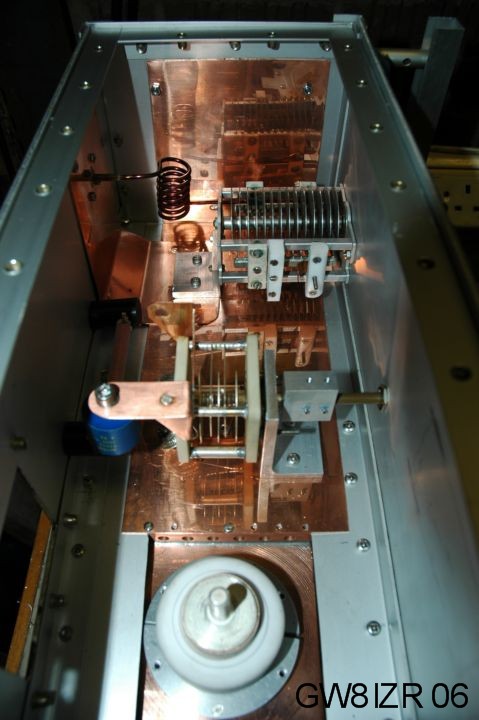
The amplifier seen from above shows the tank coil in place. This was fabricated from 3/16" copper brake pipe. A trick picked up from one of the amplifier reflectors was to place a
temporary resistor to ground across the valve to simulate the standing load resistance when in operation. By using a network analyser looking back into the anode compartment it was possible to make the coil with exactly the right value.
Subsequently with HT volts applied it was not necessary to change its value at all.
A closer view of the anode compartment here shows the HV divider chain behind its RF screen, this is the resistor chain that signals HV OK to the control board and allows the amplifier to run.
Along with many other constructors I use the simple and reliable
Triode Board
from Ian GM3SEK. The metering and protection provided by this board is excellent so dont try to re invent the wheel!
The board is easy to test and the protection is calibrated before attaching any high voltages, so protection of the valve and PSU is imediate.
The point to point wiring makes for a reliable setup and easy to remove the board should service be required.
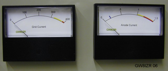
Making custom meter scales was never easier -
Tonnesoft will take you to Jim's page where
the software used here is available, multiple scales and complex layouts are a breeze with this package. If you do nothing else, checkout this page as Jim's software is very useful.
So .. its finished, well nearly. There is a little investigation to do around the grid choke and cathode choke arrangement.
I might look at replacing the anode dc blocking cap as it's a surplus item that might not be perfect, but it hasn't got warm yet. At some point all of my projects become a little " I might just do this.. I might just do that ...." where in reality I should
just get on with enjoying using it.
Does it work, yes it does.. just 60W of drive delivers a nice clean 1.5Kw and the thru insertion loss is spot on. The input match is good and nothing apart from the dummy load gets hot. On air reports confirm what the analyser tells me which is very satisfying.
More HT would probably scrape a few more watts from this amp but there is nothing really to be gained from this. I have a number of tubes that need testing and
it will be interesting to see how they all fare in this deck. For the record these measurements are made using a Fluke bench DVM and RF measurements using a directional coupler / HP437 power meter. Amplifier terminated into a Bird Termaline.
Tube No1
4.1Kv @ 750mA Anode : DC input 3075W
Tube No 2
5Kv @ 670mA Anode : DC input 3350W
In both situations anode dissipation is well within the ratings of the tube at just less than 1.3Kw but the plate voltage is much higher than the ratings, so take care if you decide to do this.
Tube number two was installed in May 2009 and was a result of some miss diagnosis here.
I had originally thought that I had killed the tube when I raised the HT to 5Kv and strange changes in tuning occured under full power.
In fact the tube was fine and it was actually a Russian ceramic door knob capacitor breaking down, this failure was a result of the anode RFC being too small
in the first place. The new RFC has 10X more reactance and the new bypas C is fine.
Generally the air temperature at the exhaust is 41c at this level rising to 50c after ten minutes key down ( 26c ambient )
It isn't required to retune when moving +/- 75KHz - beyond that a touch of the tune control helps.
As expected the tubes get better and better with carefull restoration before use.
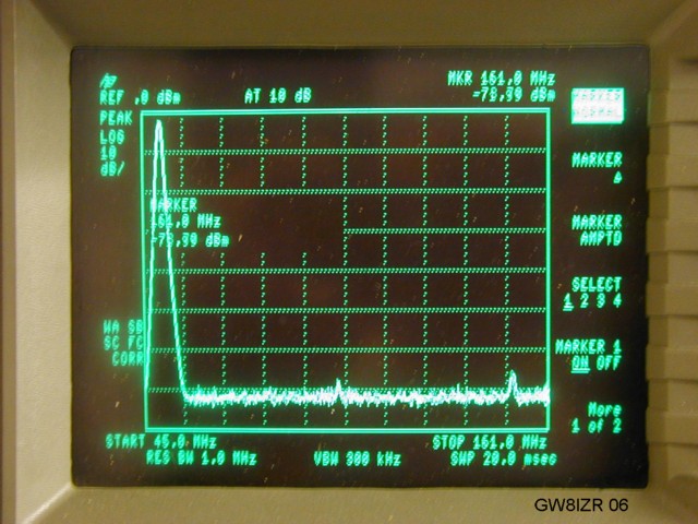
Here it is sitting on its rack in final test. 60W drive for 1500W out. The plot from the analyser is the raw output from the amp at 1500W 2F -67dbc 3F -65dbc ( factoring slope of directional coupler )
All of my amplifiers get a name, this name comes from the inspiration used during design, implementation and the source of comfort when it goes wrong. This one is called The Glenlivet.
What's next.. ?


90W RF drive 310mA grid current delivers 1.8Kw out
55% efficient which I consider good enough at this level.
100W RF drive 300mA grid current delivers 2.1Kw out
59% efficient.
After some general improvements this amplifier works well at 1.6Kw out.
Input match is flat enough from 49Mhz to 52Mhz and does not need adjustment as you move round the band, obviously its better where it's tuned